The project
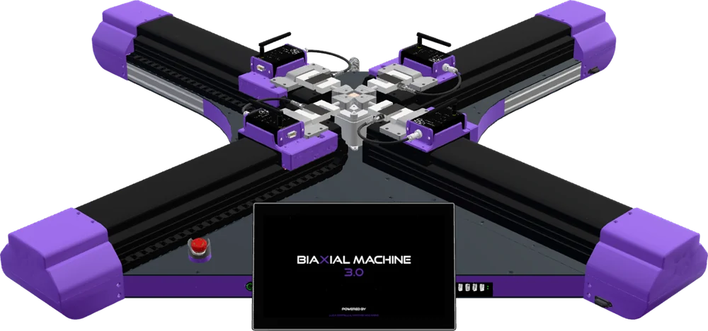
A biaxial tensile testing machine designed mainly for textiles and, in particular, for painting canvases. The specimen is loaded in two directions at the same time and its response is measured: information that helps conservators understand how historical materials behave and plan their treatments.
The machine was created for Antonio Iaccarino’s PhD research project at Delft University of Technology, in the Netherlands, where the first two revisions were used. Revision 3.0 builds on that experience with a sturdier, easier-to-use machine that has already been used to test samples of historical canvases.
Development is shared. Luca Cortelli designs and builds the machine: structure, mechanics, electronics, measurement board firmware, PLC logic and operator software. Antonio Iaccarino, drawing on many years of experience in research and conservation, defines the types of experiment and the test protocols and oversees their validation.
The project is open source, with the aim of building a community of conservators, researchers and laboratories around the machine who can use it, improve it and share methods and results.
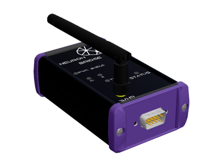
Four opposed actuators load the specimen along X and Y, together or separately. Each actuator has its own load cell, read by a Neuron Bridge board mounted on the carriage: the PLC controls each axis in position or force and logs force, position, temperature and humidity in a single test file.
The same bench handles several types of test: the configuration is selected from the operator panel and the grips suited to the specimen are fitted.
At a glance
- Tests on textiles and canvases, including historical ones
- Biaxial, uniaxial on X or Y, compression and bending on a single axis
- 1.5 kN per axis, 600 mm stroke per axis, speed 1–900 mm/min
- Position, force and force-feedback control
- CODESYS PLC on Raspberry Pi 4, OPC UA to HMI and external systems
- Operator interface Cortex Interface on a 13″ touch panel
- Created for Antonio Iaccarino’s PhD at TU Delft
- Open source, for a conservation community
How it is built
Scroll: the machine comes apart one assembly at a time, from the base to the test.
Loading the 3D model
BIAXIAL MACHINE REV. 3.0
01 / 09
The machine
A cross of four axes on a 1200 × 1200 mm base: the specimen in the centre, the operator panel on one corner.
- X-axis actuatoriCS-RS2323 motor · 5 mm lead ball screw
- Load cell and Neuron BridgeOne per actuator · 24-bit ADC
- Grips and specimen10, 25 and 100 mm specimens
- Operator panel13″ touch · Cortex Interface
- Emergency stopMushroom-head button
02 / 09
The structure
Two 3 mm steel plates, spaced 40 mm apart by 2040 aluminium profiles, form a light, stiff double-skin base, sized to withstand a tensile force of 1.5 kN per axis.
03 / 09
The actuators
Four linear axes, two opposed in each direction. Each one has a Leadshine iCS-RS2323 closed-loop stepper motor with integrated drive and encoder, a ball screw with 5 mm lead and HGR15 recirculating ball guides. 300 mm stroke per actuator, positioning to a hundredth of a millimetre.
04 / 09
Force measurement
Each actuator carriage carries the load cell and its Neuron Bridge board. The board reads the strain-gauge bridge with a 24-bit converter and sends the force in newtons over Modbus RTU: the analogue signal travels only a few centimetres before becoming digital data.
05 / 09
Electronics and controls
Under the cover, between the two plates, sit a USB hub, the USB converter to four RS485 lines, one for each motor and load cell pair, the Modbus I/O expansion and the wiring distribution. On the operator side: 13″ touch panel, emergency stop, status buttons, USB and Ethernet ports and the sensor that logs temperature and humidity during the test.
- USB hubAdditional USB ports
- I/O boardInputs and outputs over Modbus
- RS485 converterUSB to 4 lines, one per axis
- T/RH sensorCWT-TH03S-H, next to the specimen
06 / 09
Grips and specimen
In the centre, four clamping grips hold the specimen on its four sides and accept 10, 25 and 100 mm specimens. During mounting, the central part of the support rises to the level of the grips and holds the specimen in place until the clamps are closed.
07 / 09
The test
Once the specimen is mounted, the central support lowers again and the test begins: the actuators move away from the centre in a coordinated way and the specimen stretches in both directions. The PLC continuously updates the control of each axis and logs force and position every 50 ms.
08 / 09
A simple interface
The test is set up and followed from the 13″ touch panel with Cortex Interface: choose the configuration, load a recipe and start. Forces and positions of the four axes are plotted in real time on force–displacement charts; at the end of the test the report is generated automatically and the data are exported to CSV.
09 / 09
Ready for the lab
A 1 kW single-phase supply and a 1200 × 1200 mm footprint: it sits on a laboratory bench and connects to the local network for optional remote access and updates.
Test configurations
Four configurations, selected from the operator panel. In all of them the test speed ranges from 1 to 900 mm/min.
01 / 04
Biaxial
All four actuators work: the specimen is pulled along X and Y at the same time. Position, force or force-feedback control, up to 1.5 kN and 600 mm of stroke per axis.
02 / 04
Uniaxial X
Tension along a single axis with the two X actuators. The Y actuators stay still. Position or force control, up to 1.5 kN.
03 / 04
Uniaxial Y
Like the uniaxial X test, on the other axis: the two Y actuators work.
04 / 04
Single axis
A single actuator pushes the specimen against a fixed turret, for compression and bending tests. Stroke up to 300 mm.
Control architecture
How the PLC, actuators, measurements and operator communicate.
01 / 04
The PLC
A Raspberry Pi 4 running the CODESYS 3.5 runtime coordinates the machine. Each motor and load cell pair is an independent instance of the program; the PLC synchronises them and controls each axis in position or force.
02 / 04
Four RS485 lines
Each actuator has its own Modbus RTU line at 115,200 baud, shared only by its motor and its Neuron Bridge board. The four lines work in parallel: a data exchange with a drive takes about 3 ms.
03 / 04
The ambient sensor
A fifth, separate line carries the laboratory temperature and humidity, logged together with the data of every test.
04 / 04
OPC UA to the operator
The OPC UA server built into the PLC exposes test commands, setpoints, machine status, measurements and alarms. It is used by Cortex Interface on the touch panel, and through the same interface the machine can talk to PCs and systems on the local network.
Specifications
Revision 3.0 data.
Performance
| Configurations | Biaxial, uniaxial X, uniaxial Y, single axis |
| Maximum force | 1.5 kN per axis (fitted 25 kg cells ≈ 245 N) |
| Stroke | 300 mm per actuator, 600 mm per axis |
| Test speed | 1–900 mm/min |
| Maximum acceleration | 5000 mm/s² |
| Specimens | 10 × 10, 25 × 25, 100 × 100 mm |
| Maximum distance between grips | 500 mm, depending on the grips fitted |
Structure and mechanics
| Frame | Double 3 mm steel plate, spaced 40 mm with 2040 aluminium profiles |
| Guides | HGR15 recirculating ball guides |
| Transmission | Ball screw, 5 mm lead |
| Footprint | 1200 × 1200 × 300 mm |
Actuation
| Motors | 4 Leadshine iCS-RS2323, closed-loop hybrid steppers, NEMA 23 flange |
| Holding torque | 1.9 N·m |
| Encoder | Integrated 14-bit magnetic incremental |
| Positioning resolution | 0.01 mm |
| Drive functions | Homing, software limits, JOG, quick stop, 16 programmable positions |
Measurement
| Force | 1 load cell per actuator, accuracy 0.05 % of full scale, resolution 0.05 N |
| Force acquisition | Neuron Bridge with 24-bit NAU7802 ADC, 10–80 samples/s |
| Digital filters | Pyramid average, moving average, outlier rejection |
| Position | Motor encoders, 0.5 µm resolution |
| Ambient | CWT-TH03S-H: −40…+120 °C (±0.5 °C), 0–100 % RH (±5 %) |
| Logging | Force and position every 50 ms, CSV export |
Control and communication
| PLC | Raspberry Pi 4 with CODESYS 3.5 runtime |
| Control modes | Position, force, force feedback |
| Internal bus | Modbus RTU over RS485: 4 lines at 115,200 baud plus 1 line for the T/RH sensor |
| External | Built-in OPC UA server, Ethernet, USB, remote access from the local network |
| HMI | 13″ touch panel, Cortex Interface: test recipes, automatic report, force–displacement charts, multilingual |
Power and safety
| Power supply | Single-phase 110/230 V, 50/60 Hz, 1 kW |
| Upstream protection | Residual current circuit breaker |
| Safety | Emergency stop, limit switches on every actuator, software limits on force, stroke and speed, overload stop |
| Maintenance | Reduced-speed mode |
| Operating conditions | Laboratory, 10–35 °C, 0–70 % RH non-condensing |
Components
| Machine | Base with electrical cabinet, operator panel with Cortex Interface, 4 × 25 kg load cells |
| Accessories | Grips for 10, 25 and 100 mm specimens, load cells up to 1.5 kN, turret for compression and bending |
Download
| Code | Document | Rev. | Format | Status |
|---|---|---|---|---|
| BX-DS | Biaxial machine technical specifications | A | PDF · 148 KB | Download |
| BX-HMI-MAN | Cortex Interface manual for the biaxial machine | – | In preparation |
The other project documents will be available for download from this table as soon as they are ready, with code and revision.
In the lab
Photos of the machine at work.
Photos coming soon.
The project team
The people developing the biaxial machine.

Luca Cortelli
Design and build
Designs and builds the machine: structure, mechanics, electronics, measurement board firmware, PLC logic and operator software.