Neuron Bridge line
A base board that connects the field to industrial protocols. With different shields, communication modules and enclosures, it becomes a different device every time.
1product
In the line
Overview
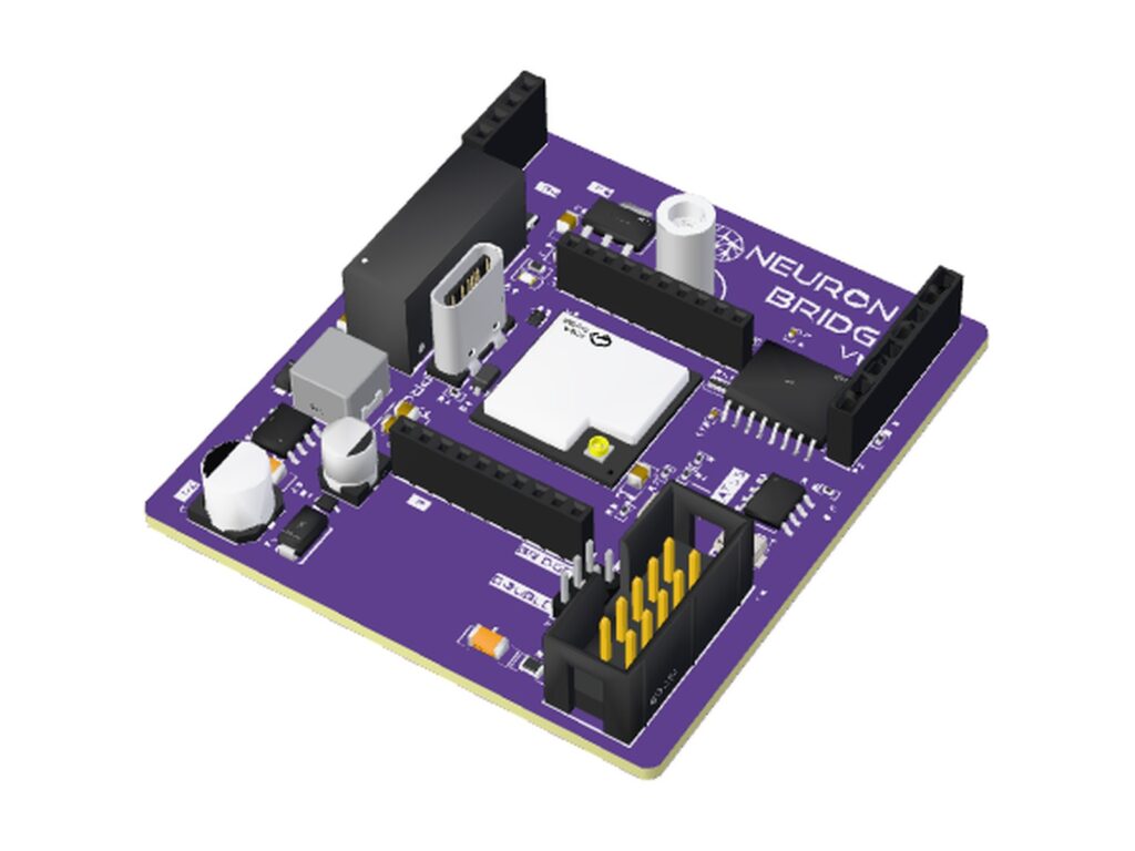
Neuron Bridge is the line of devices built on the Cortex modular platform for industrial data acquisition and communication. All configurations start from the same base board, powered directly from the 12–36 V DC field supply, with galvanic isolation between the field section and the control logic.
The architecture separates function from protocol: the shield defines the interface to the process, for measurement or actuation; the communication module defines the protocol on the fieldbus. Combining base board, shield, module and enclosure yields different devices on a single hardware platform.
The ESP32-S3 microcontroller integrates 2.4 GHz Wi-Fi and Bluetooth LE: in addition to the wired bus, the device makes data available on the network via MQTT, Modbus TCP, WebSocket and API.
Features
- Dual-core ESP32-S3 MCU with Wi-Fi and Bluetooth LE
- 12–36 V DC field power supply with input protection
- Galvanic isolation between field section and logic
- Interchangeable shields for measurement and actuation
- Interchangeable communication modules with automatic detection
- USB-C with integrated JTAG debugging
How it's built
Scroll: the device is assembled one piece at a time, from the base board to the finished product.
Loading 3D model
NEURON BRIDGE V1.0
01 / 05
Where it all begins
The brain common to every configuration: ESP32-S3 microcontroller with Wi-Fi and Bluetooth LE, 12–36 V DC field power supply, galvanic isolation between field and logic. Everything else is built around it.
- ESP32-S3ESP32-S3-MINI-1U module · 2.4 GHz Wi-Fi, Bluetooth 5 LE
- Power sectionProtected 12–36 V DC input · 600 mA isolated DC/DC
- Digital isolators5000 Vrms · CMTI ≥ 85 kV/µs
- 10-way IDC bus connectorModbus RTU, CAN · adapters for RJ45 and D-Sub 9
- Topology jumpersPoint-to-point or daisy-chain bus
- Communication module slot6 configurable lines: RS485, SPI, GPIO
- Shield connector3 IN, 3 OUT, isolated I²C and SPI
- USB-CProgramming and integrated JTAG debugging
- Indicators and controlsRGB status LED, BOOT and RESET buttons
02 / 05
The shield: the interface to the physical world
The shield gives the device its job: measurement, acquisition or control. It is a self-contained module that plugs into the expansion connector and can be custom-designed for the application, without modifying the base board. In this example, a load cell shield.
03 / 05
The communication module: the voice to the plant
The module plugs into its slot and defines the protocol on the fieldbus; the board detects it automatically at power-up. Changing protocol means changing the module, not the device. In this example, an RS485 module for Modbus RTU.
04 / 05
The enclosure: built for the environment
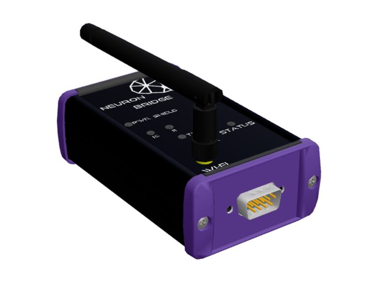
The enclosure is chosen to suit the installation environment, from the electrical cabinet to the open field: enclosures with different IP protection ratings can be built to meet the needs of the application.
05 / 05
Ready for action
The device is complete: it collects signals from the field and delivers them to the bus and the network. The interface connectors adapt to the plant, not the other way around: D-Sub, industrial circular connectors or whatever standard is already used on the cables. In the example, load cells on GX12, Modbus RTU on D-Sub 9 and Wi-Fi for configuration. The available configurations are shown below.
Configurations
The devices in the line: the same base board, with shield, communication module and enclosure chosen for the application. Each configuration has its own datasheet and documentation.
Base board specifications
Data common to all configurations, referring to hardware revision V1.0. Shield, communication module and enclosure are described on the product page of each configuration. Preliminary values, subject to confirmation in the official datasheet.
Processing
| Microcontroller | ESP32-S3 (ESP32-S3-MINI-1U-N8 module) |
| CPU | Dual-core Xtensa LX7, up to 240 MHz |
| Memory | 512 KB SRAM, 8 MB Quad SPI flash |
| Antenna | External, W.FL (MHF III) connector |
Power supply
| Input voltage | 12–36 V DC |
| Protections | 40 V / 400 W TVS, reverse polarity, PTC on the isolated output |
| +5 V output (field) | up to 2 A total |
| +5 V ISO output | 600 mA |
| USB power | 5 V, logic section only |
Isolation
| Digital I/O | 5000 Vrms, reinforced isolator |
| I²C bus | 2500 Vrms |
| Power supply | Isolated DC/DC converter |
| CMTI (digital I/O) | ≥ 85 kV/µs |
Communication
| Wireless | Wi-Fi IEEE 802.11 b/g/n 2.4 GHz, Bluetooth 5 LE |
| Network protocols | MQTT, Modbus TCP, WebSocket, API |
| Wired protocols | Modbus RTU, CAN (via communication module) |
| Bus connector | 10-way IDC, with adapters for RJ45, D-Sub 9 and others |
| Bus topology | Point-to-point or daisy chain, selectable via jumpers |
Communication module slot
| Configurable lines | 6, as RS485 UART, SPI or GPIO |
| Module identification | Automatic at power-up |
| Available supplies | +5 V ISO, +3.3 V ISO |
Shield interface
| Digital inputs | 3, isolated, 5 V level |
| Digital outputs | 3, isolated, push-pull, 5 V level |
| Serial buses | Isolated I²C up to 1 MHz, 5 V SPI |
| Available supplies | VCC 12–36 V, +5 V |
| Available shields | Load cells |
Board
| Dimensions | 54.5 × 60 mm |
| USB | USB-C, USB 2.0 Full-Speed, ESD protection |
| Indicators | Power LED, RGB status LED |
| Controls | BOOT and RESET buttons |
| Test points | 6, on supplies and grounds |
| Hardware revision | V1.0 |
Download
| Code | Document | Rev. | Format | Status |
|---|---|---|---|---|
| CX-NB-DS | Neuron Bridge technical specifications | 1.0 | PDF · 709 KB | Download |
Technical specifications of the base board, hardware revision V1.0. Installation and integration documentation is supplied with each configuration in the line.
Fieldbus
The fieldbus interface is available on a 10-way IDC connector. Connection to the plant is made with adapter cables, which route the line to the connector required by the wiring (RJ45, D-Sub 9 or others) without any change to the board.
With multidrop protocols, such as Modbus RTU over RS485 and CAN, the connection topology is selected with jumpers on the board:
- Point-to-point: the bus line is connected directly to the communication module. This is the configuration for a direct connection to a master or for the end-of-line node.
- Daisy chain: the line enters on the IN conductors and leaves on the OUT conductors of the same connector. Outbound and return runs share the same multicore cable, so each node is inserted in series on the backbone. The network keeps a linear topology, with no stubs that degrade signal integrity.
Contact
Do you need a custom version or technical support?
Write what you need to connect and on which machine: you will receive a technical reply.